


Framed or unframed, desk size to sofa size, printed by us in Arizona and Alabama since 2007. Explore now.
Shorpy is funded by you. Patreon contributors get an ad-free experience.
Learn more.


- John Vachon
- All the chairs were bought
- Passenger seat
- The two front doors
- You are correct Dave.
- I was just there
- New to me
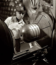
- Football-shaped thing
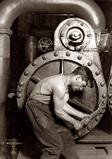
- Working all the live long day
- How do you stop slackers?
- It's [not] a Diamond T
- A Red Brown Truck
- Not Too Long a Long Walk
- What Tribe? Huh?
- Cheap labor
- No Mel Brooks fans?!?
- The real "Gandy"
- @louJudson
- Somethings not right
- Bathtubs at the barbershop
- Straining or laughing?
- Heavy!
- I don't like the look of that supervisor
- What tribe? Which rail location?
- How many do they need?
- Pursed lips
- Another lost street trade?
- Where Is The Carpet bag?
- Another great composition
- The Un-Coaler

Photos submitted by Shorpy members!
Printporium


A Series of Tubes: 1923

Washington, D.C., circa 1923. "Herbert Hoover Jr. radio set." Seen here yesterday with the son of the future president. View full size.
Talking to Europe
TheGeezer has the ID on the transmit/receive switch; I couldn't see it in yesterday's photo and ventured that the the 4-pole knife switch (to the right of the telegraph key) was the T/R.
Looking at it today, I think the 4-pole knife switch probably controls at least the filament power to the transmitter. It looks like there is another meter just behind this switch, which probably monitors the filament voltage or current. I don't know whether this 4-pole switch would have been closed all the time when the set was operating, or whether it had to be closed to transmit and open to receive.
It was only in 1921 that the first one-way ham transmissions from US to Europe with tube transmitters happened. In late 1923, two US hams were able to talk to one French ham. Young Herbert may have been part of this effort at trans-Atlantic communications. They were working around 1.5 MHz, or the upper part of today's AM broadcast band. (More history here.)
The closest modern ham band is 160 meters, or 1.8 to 2.0 MHz. A radio for that band that replaces everything on this table looks like this. It can transmit and receive in both CW (Morse code) or voice, and handle 10 other bands as well. You can use it in a fixed installation, or with a bit of care, install it in your car and drive around. It doesn't look as cool, though.

Mullard Valves
On the right, a U30 Rectifier similar to the Mullard tube in our photo.

It's an antenna
The strap descending from the window seems to be connected to the pole of a switch (the part of the switch that is movable, with the large black handle). The large coil appears to be connected through a meter to one side of the switch. That would make it a radio-frequency (RF) ammeter, which the operator used to tune the coupled coils, using variable capacitors, to the desired frequency. It appears the coil coupling could REALLY be varied to control loading of the transmitter RF onto the antenna system.
The other side of the switch connects to a wire, which likely fed the antenna input of the receiver. The handle switched the antenna connection to the transmitter and receiver.
Big stuff, this.
On Shorpy:
Today’s Top 5